


ARTICLE CONTENTSOn this page 10 sections
Simple Repairs
Performance Objectives
By the end of the lesson, students should be able to:
- explain assembling and disassembling of a computer and mobile phone components;
- trace faulty components of computer/mobile phone by inspection and testing;
- state the procedures for fixing faulty keypads;
- identify faulty component;
- repair faulty component;
- test component after repairs.
Introduction to Assembly and Disassembly
Assembly is the process of putting together individual hardware components to form a complete, functional computer or mobile phone system.
Disassembly is the systematic process of taking apart a computer or mobile phone system into its individual hardware components.
Understanding these two processes is fundamental to hardware maintenance and repair. It allows technicians to access internal parts, replace damaged components, and upgrade systems safely without causing further damage to the device.
Tools and Safety Equipment for Repairs
Performing repairs on computers and mobile phones requires specialized tools and safety equipment to protect both the technician and the sensitive electronic components. Electrostatic discharge (ESD) and physical injuries are common risks during hardware repairs.
The essential tools and safety equipment used in a hardware workstation include:
- Screwdrivers: Precision screwdrivers of various sizes and types, such as Phillips, Torx, and flathead, are used to loosen and tighten screws holding the device chassis and internal components.
- Pliers: Small needle-nose pliers are used to grip, bend, or pull small wires and components in tight spaces.
- Testers (Multimeters): Electronic measuring instruments used to test voltage, resistance, and continuity in circuits to identify broken connections or faulty components.
- Soldering Iron: A tool that provides heat to melt solder (lead wire) so that it can flow into the joint between two electrical parts to establish an electrical connection.
- Desoldering Pump (Solder Sucker): A device used to remove melted solder from a connection point during component removal.
- Lead Wire (Solder): A fusible metal alloy used to join together metal workpieces in soldering.
- Soldering Board: A heat-resistant surface or holder used to secure circuit boards safely during soldering operations.
- Soldering Flux: A chemical cleaning agent used before and during soldering to prevent oxidation and help the solder flow smoothly.
- Goggles: Protective eyewear worn to shield the eyes from flying debris, solder splashes, or chemical fumes.
- Anti-Static Wrist Strap: A device worn on the wrist to ground the technician and prevent electrostatic discharge from damaging sensitive microchips.
Assembling and Disassembling Procedures
Systematic procedures must be followed during assembly and disassembly to prevent damage to delicate circuits and to ensure that all parts are returned to their correct positions.
Disassembling a Desktop Computer
The procedure for disassembling a desktop computer involves the following steps:
- Shut down the computer, turn off the power switch at the mains, and unplug all external cables, including the power cord, monitor cable, keyboard, and mouse.
- Put on an anti-static wrist strap and connect the alligator clip to an unpainted metal surface of the computer case.
- Unscrew and remove the side panel of the computer case to expose the internal components.
- Disconnect all power cables running from the Power Supply Unit (PSU) to the motherboard, storage drives, and fans.
- Disconnect all data cables, such as SATA cables, from the storage drives and the motherboard.
- Remove the Random Access Memory (RAM) modules by pressing down on the securing clips at both ends of the slots until the modules pop up.
- Unscrew and slide out the storage drives, such as the Hard Disk Drive (HDD) or Solid State Drive (SSD), from their bays.
- Unscrew and remove any expansion cards, such as graphics cards or network cards, from their PCI Express slots.
- Unscrew the motherboard from the case standoffs and carefully lift it out of the chassis.
- Unscrew and remove the Power Supply Unit from the case.
Assembling a Desktop Computer
The procedure for assembling a desktop computer involves the following steps:
- Mount the Power Supply Unit into the computer case and secure it with screws.
- Install the processor (CPU) and the CPU heatsink/fan assembly onto the motherboard before placing the motherboard in the case.
- Align the motherboard ports with the Input/Output (I/O) shield at the back of the case, place the motherboard onto the standoffs, and secure it with screws.
- Insert the RAM modules into their slots, pressing down firmly until the side clips snap into place to lock them.
- Install the storage drives into their respective bays and secure them with screws or toolless brackets.
- Insert expansion cards into their motherboard slots and secure their brackets to the case frame with screws.
- Connect the main 24-pin power cable and the 4-pin or 8-pin CPU power cable from the PSU to the motherboard.
- Connect the power and SATA data cables to the storage drives.
- Connect the front panel cables, including the power switch, reset switch, power LED, and hard drive LED, to the system pins on the motherboard.
- Close the side panel of the case, secure it with screws, reconnect all external cables, and power on the system to verify successful assembly.
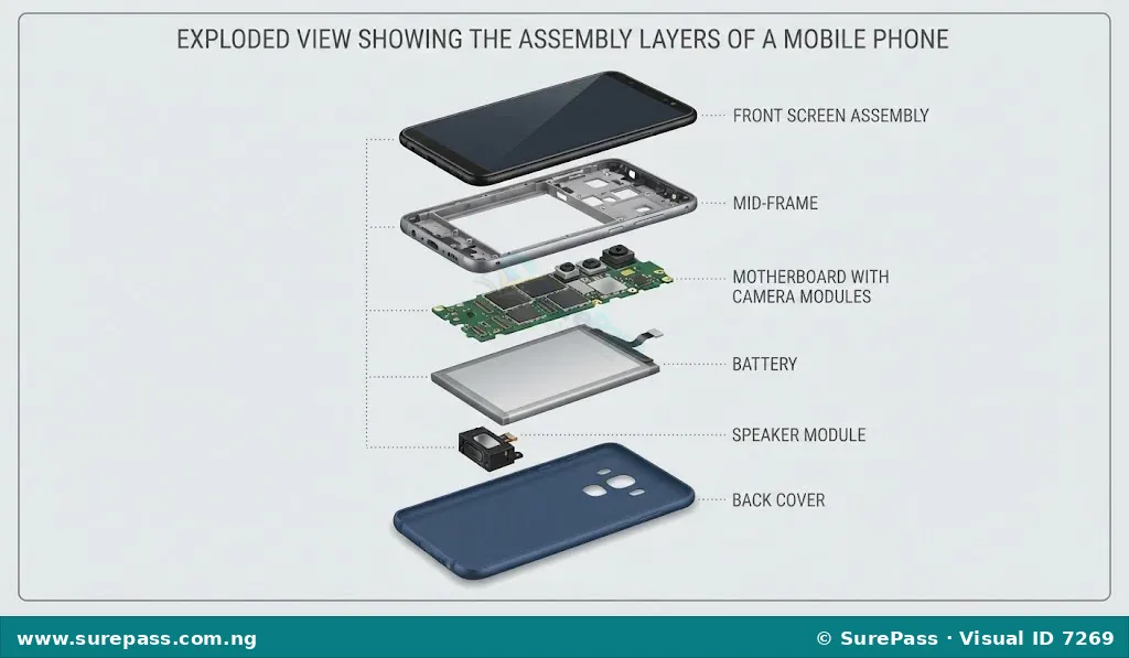
Disassembling a Mobile Phone
The procedure for disassembling a mobile phone involves the following steps:
- Power off the mobile phone and remove the SIM card tray and memory card holder using a SIM ejector tool.
- Apply gentle heat to the edges of the back cover using a heat gun or hot plate to soften the adhesive holding it in place.
- Place a suction cup on the back cover, pull upward slightly to create a small gap, and insert a thin plastic opening tool or guitar pick.
- Slide the plastic tool carefully around the perimeter of the back cover to slice through the adhesive, then lift the back cover off.
- Unscrew the protective metal or plastic brackets covering the motherboard and battery connectors.
- Use a plastic spudger to disconnect the battery flex cable from the motherboard to cut off power to the circuits.
- Disconnect all other ribbon cables, including the display flex cable, charging port cable, and front/rear camera connectors.
- Unscrew and carefully lift the motherboard out of the phone frame.
- Remove modular components such as the speaker, vibrator motor, and front camera from their designated slots.
- Apply heat to the front screen assembly to soften the adhesive, then use a plastic pry tool to separate the damaged screen from the frame.
Assembling a Mobile Phone
The procedure for assembling a mobile phone involves the following steps:
- Clean the phone frame thoroughly to remove any old adhesive residue.
- Apply new adhesive tape or liquid adhesive along the edges of the frame where the screen will sit.
- Feed the display ribbon cable through the frame opening, align the new screen assembly with the frame, and press it down gently but firmly.
- Place the motherboard back into the frame and secure it with its designated screws.
- Reconnect all ribbon cables, including the display cable, charging port cable, and camera modules, to their motherboard sockets.
- Insert the modular speaker and vibrator motor back into their positions.
- Connect the battery flex cable to the motherboard as the final electrical connection.
- Reinstall the protective metal or plastic brackets over the motherboard and tighten the screws.
- Apply adhesive to the back cover frame, align the back cover, and press it down to seal the phone.
- Insert the SIM card tray, power on the device, and verify that the display, touch response, and speaker function correctly.
Component Inspection, Identification, and Testing
Before attempting any repair, a technician must inspect and test the device to identify the exact faulty component. This prevents unnecessary replacement of working parts.
Inspection Techniques
Inspection involves using the senses to detect physical abnormalities in hardware components. The two primary methods are:
- Visual Inspection: Looking closely at components for signs of damage. On a motherboard, this includes looking for burnt chips, leaking or bulging capacitors, broken solder joints, or corrosion from liquid spills. On screens, it involves checking for cracks, scratches, or bleeding pixels. On keypads, it involves checking for worn-out keys or torn membranes.
- Physical Inspection: Feeling or smelling components. This includes checking for excessive heat generation on chips immediately after powering on, feeling for loose connectors, or smelling for burnt plastic or electrical components.
Testing Techniques
Testing involves using diagnostic tools to measure electrical properties and verify if a component is functioning within its specifications.
The main testing procedures include:
- Continuity Testing: Using a multimeter set to continuity mode (which beeps when a complete path is detected) to check if a wire, ribbon cable, or circuit track is broken. If the multimeter does not beep when the probes touch both ends of a track, the path is broken.
- Resistance Testing: Measuring the resistance of components like speakers or resistors. A working speaker typically has a low resistance (usually between 4 and 16 ohms). A reading of infinity (open circuit) indicates a blown speaker coil.
- Voltage Testing: Measuring the voltage output of power sources, such as batteries or power adapters, to ensure they are delivering the correct amount of electrical power to the device.
Identification of Faulty Components
Specific symptoms point directly to particular faulty components. The table below outlines common symptoms and the corresponding faulty parts:
| Component | Common Symptoms of Failure | Method of Identification |
|---|---|---|
| Keypad / Keyboard | Keys are unresponsive, sticky, double-type characters, or register incorrect characters. | Visual inspection for dirt/liquid; software keyboard test; continuity test on key contacts. |
| Speaker | No sound output, distorted or crackling sound, very low volume even at maximum settings. | Audio playback test; resistance test using a multimeter (checking for open circuit). |
| Screen (Display) | Cracked glass, black screen with backlight on, vertical or horizontal lines, bleeding ink effect, unresponsive touch. | Visual inspection for physical cracks; external monitor test (for computers); touch diagnostic tool. |
Procedures for Fixing Faulty Components
Once a component has been identified as faulty, specific repair procedures must be followed to restore functionality.
Procedures for Fixing Faulty Keypads
Keypad failures are often caused by dirt, liquid spills, or worn-out conductive pads. The procedure for fixing a faulty keypad involves the following steps:
- Disassemble the device to access the keypad assembly or keyboard module.
- Remove the keycaps or the rubber membrane overlay carefully.
- Dip a cotton swab in isopropyl alcohol (99% concentration) and gently clean the black conductive carbon pads on the underside of the rubber membrane.
- Clean the corresponding copper contact pads on the printed circuit board (PCB) to remove dirt, grease, or corrosion.
- Allow the alcohol to evaporate completely.
- If the conductive carbon on the rubber pad is worn out, apply a small amount of conductive graphite paint or a conductive keypad repair pad to the underside of the key.
- Reassemble the keypad, connect it to the device, and test the keys for responsiveness.
Procedures for Fixing a Faulty Speaker
Speaker faults are usually caused by torn diaphragms, loose connections, or burnt voice coils. The procedure for fixing or replacing a speaker involves the following steps:
- Disassemble the computer or mobile phone casing to locate the internal speaker module.
- Inspect the speaker wires or contact spring pins. If the spring pins are bent, use tweezers to gently bend them back to their original height to ensure proper contact with the motherboard.
- If the speaker wires are detached from the board, use a soldering iron and lead wire to solder the wires back onto their respective positive (+) and negative (-) pads on the circuit board.
- If the speaker coil is burnt (indicated by an infinite resistance reading on a multimeter), desolder the old speaker connections or lift the modular speaker out of its housing.
- Place a new speaker of identical specifications (impedance and physical size) into the housing.
- Solder the new speaker wires to the board or align the contact pins with the motherboard pads.
- Reassemble the device and play an audio file to test the sound quality.
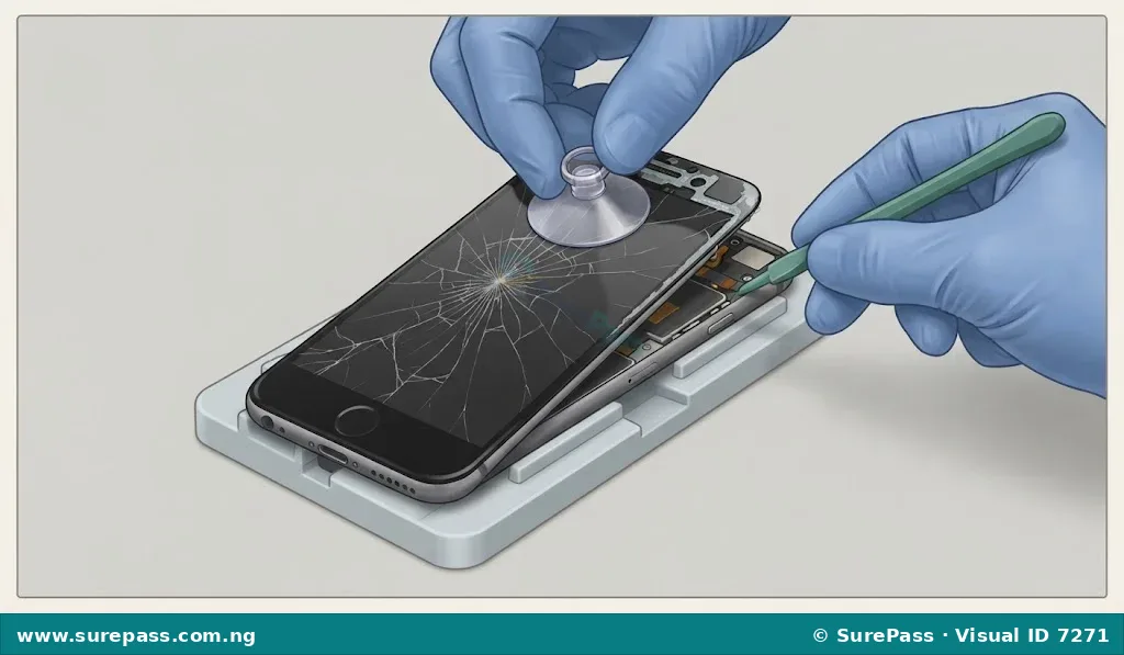
Procedures for Replacing a Damaged Screen
A cracked or bleeding screen cannot be repaired and must be replaced with a new display panel. The procedure for replacing a damaged screen involves the following steps:
- Power off the device and disconnect the battery to prevent electrical short circuits.
- Use a heat gun to apply uniform heat around the edges of the screen to soften the adhesive holding the screen to the frame.
- Apply a suction cup to the screen, pull upward gently, and insert a thin plastic pry tool into the gap.
- Slide the pry tool carefully around the edges to separate the screen from the frame, taking care not to damage internal cables.
- Carefully lift the screen and disconnect the display ribbon cable from the motherboard connector.
- Remove the damaged screen and clean all remaining adhesive residue from the frame using isopropyl alcohol and a plastic scraper.
- Connect the ribbon cable of the new screen to the motherboard and temporarily reconnect the battery to test the display before final sealing.
- Power on the device to check for display alignment, brightness, and touch responsiveness.
- Power off the device, disconnect the battery, apply new adhesive tape or liquid adhesive to the frame, and press the new screen firmly into place.
- Reassemble the remaining components, clamp the screen gently for 30 minutes to allow the adhesive to cure, and perform a final system test.
Testing Components After Repairs
Testing after minor repairs is essential to confirm that the fault has been resolved and that no new issues were introduced during the assembly process.
The systematic testing process includes:
- Power-On Self-Test (POST) Observation: For computers, observe the boot process to ensure the system detects the keyboard and display without displaying error codes or emitting warning beeps.
- Keypad/Keyboard Functional Test: Open a text editor or diagnostic software and press every key systematically to ensure they all register correctly and do not stick.
- Audio Output Test: Play a standard audio file or ringtone. Listen for clarity, volume level, and the absence of distortion or crackling noises from the speaker.
- Display and Touch Test: Inspect the screen for uniform brightness, correct color reproduction, and the absence of lines or dead pixels. For touchscreens, drag an icon across the entire surface of the screen to ensure there are no dead zones in touch sensitivity.
- Physical Integrity Check: Inspect the device exterior to ensure all screws are tight, panels are properly aligned, and there are no gaps in the casing.
Summary of Repair Workflow
A successful repair follows a logical sequence of steps to ensure safety and efficiency. The diagram below illustrates the standard workflow from initial diagnosis to final testing.
Review Questions
The following questions are designed to test the understanding of the concepts covered in this unit:
- Define the terms assembly and disassembly in relation to computer hardware.
- List five essential tools required at a hardware repair workstation and state their uses.
- Describe the step-by-step procedure for disassembling a desktop computer safely.
- Explain how a technician can identify a faulty mobile phone speaker using a multimeter.
- Outline the procedure for cleaning and fixing a sticky or unresponsive keypad.
- Why is it important to disconnect the battery before replacing a mobile phone screen?
- State three tests that should be performed on a mobile phone after replacing its screen.



0 comments
Open the discussion when you need it. Comments stay collapsed until requested so the initial article remains light.