



ARTICLE CONTENTSOn this page 9 sections
Diagnostics Steps
Performance Objectives
By the end of the lesson, students should be able to:
- demonstrate the use of software codes for fault finding on a computer and mobile phone;
- carryout fault-finding procedures to identify related problems in computer and mobile phones;
- explain use of multi-meter and computers in tracing fault in computer and mobile phone.
Introduction to Diagnostics and Fault Finding
Diagnostics is the systematic process of identifying the nature and cause of a hardware or software failure in a device.
Fault finding is the practical act of locating and isolating the specific component or circuit responsible for a device malfunction.
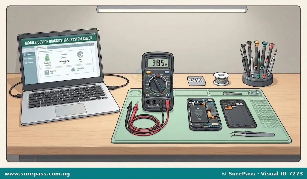
In computer hardware and GSM repairs, diagnostics and fault finding form the foundation of successful maintenance. Before any physical repair or component replacement is carried out, a technician must accurately determine where the fault lies. This prevents unnecessary damage to functional parts and reduces repair time. The diagnostic process combines software-based tools, built-in hardware codes, and physical testing instruments to isolate issues in both computers and mobile phones.
Software Codes for Fault Finding
Software codes and diagnostic utilities are built-in instructions or programs used to query the hardware status of a computer or mobile phone. These codes allow technicians to perform quick, non-invasive tests to verify if specific modules are functioning correctly.
Computer Diagnostic Codes and Tools
Computers use a combination of firmware-level codes and operating system utilities to report hardware faults. The most fundamental of these is the Power-On Self-Test (POST).
The Power-On Self-Test is a built-in diagnostic program run by the computer’s firmware to check the integrity of essential hardware components before booting the operating system.
If a fault is detected during the POST, the computer motherboard communicates the error through audible beep codes or visual hexadecimal codes on a diagnostic card. Common motherboard beep codes include:
- One short beep: The system is healthy and has passed the hardware check.
- Continuous beep or repeating short beeps: This indicates a power supply unit (PSU) fault or a critical motherboard failure.
- One long beep and two or three short beeps: This indicates a video adapter (graphics card) failure or memory detection issue.
- Continuous long beeps: This indicates that the Random Access Memory (RAM) is not detected, is poorly seated, or is faulty.
In addition to POST beep codes, operating system utilities provide detailed diagnostic information. The primary diagnostic tools in the Windows operating system include:
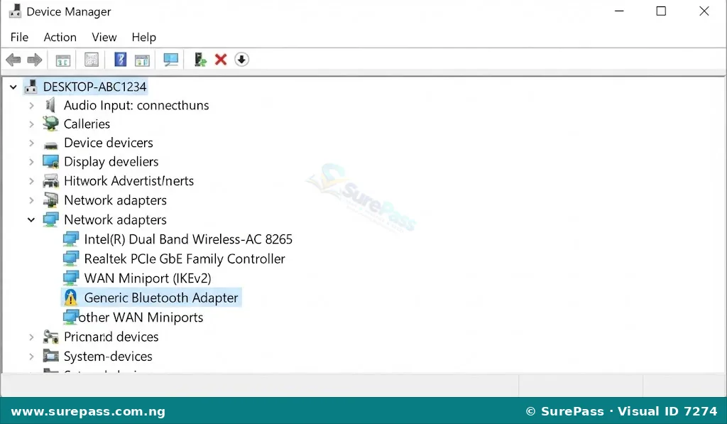
- Device Manager: A utility that displays all installed hardware devices and highlights faulty or missing drivers with a yellow exclamation mark.
- Windows Memory Diagnostic: A tool that tests the system’s RAM for physical defects and address errors.
- DirectX Diagnostic Tool (dxdiag): A utility accessed by typing “dxdiag” in the Run dialog box, used to test video, audio, and input device functionality.
- System Information (msinfo32): A comprehensive tool that displays detailed hardware resources, components, and software environments.
Mobile Phone Diagnostic Codes
Mobile phones utilize Unstructured Supplementary Service Data (USSD) codes, often referred to as secret codes or diagnostic codes. These codes are entered directly into the phone’s dialer to launch hidden hardware testing menus.
Common diagnostic codes for Android devices include:
- *#06#: Displays the International Mobile Equipment Identity (IMEI) number, which verifies baseband and modem integrity.
- #0#: Launches the general hardware test menu on many Android devices (such as Samsung), allowing testing of the LCD screen, receiver, vibration motor, camera, sensors, earpiece, and mouthpiece.
- ##4636##: Displays detailed information about the phone, battery status, usage statistics, and Wi-Fi connection details.
- ##34971539##: Displays detailed camera firmware and hardware information.
Common diagnostic codes for iOS (Apple) devices include:
- *#06#: Displays the IMEI number.
- 3001#12345#: Launches the Field Test Mode, which provides detailed information about the cellular signal strength, network tower connections, and Radio Frequency (RF) performance.
Fault Finding Procedures for Specific Components
A systematic fault-finding procedure ensures that each hardware component is tested in a logical sequence. This prevents diagnostic errors and isolates the root cause of hardware failures.
1. Central Processing Unit (CPU)
The CPU is the primary control unit of the device. CPU faults often manifest as system freezes, sudden shutdowns, or a complete failure to boot.
The fault-finding procedure for a computer CPU involves:
- Checking for overheating: Verify that the CPU cooling fan is spinning and that the heatsink is firmly attached with fresh thermal paste.
- Verifying power delivery: Measure the voltage regulators on the motherboard (VRMs) to ensure the CPU is receiving its core operating voltage.
- Testing with a known-good CPU: Swap the suspected CPU into a compatible, working motherboard to isolate whether the fault lies in the processor or the motherboard socket.
The fault-finding procedure for a mobile phone CPU involves:
- Monitoring current draw: Connect the phone to a regulated DC power supply and observe the current consumption when the power button is pressed. A stuck current draw (e.g., stable at 50mA to 80mA) often indicates a CPU communication failure with the flash memory.
- Checking for physical heat: Feel the motherboard shieldings for localized hot spots, which indicate a short circuit within the CPU or its surrounding power lines.
2. ROM and RAM
ROM (Read-Only Memory) holds the system firmware (BIOS/UEFI in computers, bootloader in phones), while RAM (Random Access Memory) holds temporary data for active processes.
The fault-finding procedure for computer ROM and RAM involves:
- Reseating the RAM modules: Remove the RAM sticks, clean the gold contacts with an eraser or isopropyl alcohol, and reinsert them firmly into the slots.
- Testing individual slots: Insert a single known-good RAM module into different slots to determine if a specific motherboard slot is faulty.
- Clearing the CMOS: Reset the BIOS ROM settings to default by removing the motherboard’s coin-cell battery (CR2032) for a few minutes.
The fault-finding procedure for mobile phone ROM and RAM (often integrated as an eMMC/UFS and LPDDR chip stack) involves:
- Observing boot loops: If the phone displays the manufacturer logo repeatedly but fails to load the operating system, it indicates a corrupted ROM firmware or a failing storage chip.
- Flashing firmware: Connect the phone to a computer and attempt to write fresh operating system firmware using authorized flashing software. If the software returns a “partition write error,” the ROM chip is physically damaged.
3. Power Supply
The power supply system converts external electrical energy into the precise voltages required by the device’s internal circuits.
The fault-finding procedure for a computer Power Supply Unit (PSU) involves:
- Performing the paperclip test: Disconnect the 24-pin ATX connector from the motherboard, bridge the green wire (PS_ON) with any black wire (GND) using a paperclip, and check if the PSU fan spins.
- Measuring output voltages: Use a multimeter to measure the voltage on the yellow wires (+12V), red wires (+5V), and orange wires (+3.3V) to ensure they are within acceptable tolerances.
The fault-finding procedure for a mobile phone power system involves:
- Testing battery voltage: Measure the battery terminals with a multimeter. A lithium-ion battery must have at least 3.7V to boot the phone.
- Inspecting the Power Management Integrated Circuit (PMIC): Check the capacitors surrounding the PMIC for short circuits to ground, which indicate a failed power management chip.
4. Charging System and Radio Frequency (RF) Sections
The charging system manages power input, while the RF section controls wireless communication, including cellular signals, Wi-Fi, and Bluetooth.
The fault-finding procedure for the charging system involves:
- Inspecting the charging port: Check the USB or charging port for physical damage, bent pins, or accumulated lint.
- Measuring VBUS voltage: Connect a charger and measure the voltage at the charging port pins on the motherboard. It should read approximately 5V DC.
- Testing the charging IC: Verify if voltage is reaching the battery connector pins when the charger is plugged in.
The fault-finding procedure for the Radio Frequency (RF) section involves:
- Checking the antenna contacts: Ensure the physical spring contacts between the motherboard and the phone’s housing antenna are clean and unbroken.
- Verifying the network settings: Check if the phone displays “No Service” or “Searching.” If the IMEI or Baseband version is blank in the settings menu, the RF processor or baseband IC is faulty.
- Measuring power supply to the RF Power Amplifier (PA): Use a multimeter to check if the PA chip is receiving its operating voltage from the battery line.
5. Mouthpiece (Microphone)
The mouthpiece converts acoustic sound waves from the user’s voice into electrical signals during calls or recordings.
The fault-finding procedure for a mouthpiece involves:
- Checking for physical blockage: Inspect the microphone port hole at the bottom of the device for dirt, dust, or phone case obstructions.
- Testing with a voice recorder app: Record a short audio clip. If the recorded waveform is flat or silent, the microphone circuit is inactive.
- Measuring continuity and resistance: Use a multimeter in resistance mode to measure across the microphone terminals. A functional analog microphone typically shows a resistance reading between 1k Ohm and 3k Ohms.
6. Earpiece (Receiver Speaker)
The earpiece converts electrical audio signals back into sound waves near the user’s ear.
The fault-finding procedure for an earpiece involves:
- Testing with a phone call: Place a call and switch between the earpiece and the loudspeaker. If sound is heard only on the loudspeaker, the earpiece or its dedicated circuit is faulty.
- Inspecting spring contacts: Ensure the earpiece speaker contacts are making firm physical contact with the motherboard pads.
- Measuring coil resistance: Use a multimeter in resistance mode to measure the earpiece speaker terminals. A healthy earpiece speaker coil should have a low resistance, typically between 8 Ohms and 32 Ohms. A reading of infinity (open loop) indicates a blown voice coil.
Diagnostic Tools: Multimeters and Computers
Professional technicians rely on external diagnostic hardware to trace faults that cannot be resolved by software alone.
Using a Multimeter in Fault Tracing
A multimeter is an electronic measuring instrument that combines several measurement functions, such as voltage, current, resistance, and continuity, into a single unit.
Multimeters are available in analogue (using a needle pointer) and digital (using an LCD screen) formats. Digital multimeters are preferred for modern electronics due to their high accuracy and ease of reading.
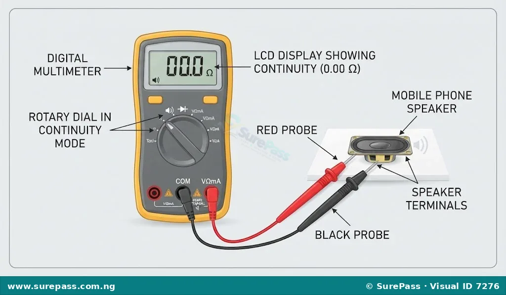
The primary measurement modes used for fault tracing include:
- Continuity Mode (Beep Test): Used to check if a copper track, wire, or fuse is broken. The multimeter emits a continuous beep if there is a complete electrical path (low resistance) between the two probes.
- DC Voltage Mode (V DC): Used to measure the voltage of batteries, charging ports, and power rails. The black probe is connected to ground (GND) and the red probe is placed on the test point.
- Resistance Mode (Ohms): Used to measure the resistance of resistors, speakers, and coils, and to check for short circuits on power lines.
Using Computers to Trace Mobile Phone Faults
A computer serves as an advanced diagnostic workstation when connected to a mobile phone via a USB data cable. It runs specialized software suites to read system logs, flash firmware, and analyze hardware states.
Computers trace mobile phone faults through the following methods:
- Device Manager Detection: When a dead mobile phone is connected to a computer, the computer’s Device Manager monitors the USB port. If the computer detects a specific chipset driver (such as MediaTek USB VCOM, Qualcomm HS-USB QDLoader, or Apple Recovery Mode), it proves that the phone’s CPU and USB interface are functional, pointing the fault toward a corrupted ROM or a dead display.
- Diagnostic and Flashing Software: Programs such as Odin (for Samsung), SP Flash Tool (for MediaTek devices), and iTunes/3uTools (for iOS) read the internal partition tables of the phone to verify if the storage memory (ROM) is readable and writable.
- Real-time Log Analysis: Software utilities read the live system logs (Logcat on Android) as the phone boots, allowing technicians to see exactly which software driver or hardware initialization step is causing the system to crash.
Practical Diagnostic Procedures
The following step-by-step procedures demonstrate how to perform diagnostic tasks on computers and mobile phones using software codes and physical testing tools.
How to Use USSD Codes to Test Mobile Phone Hardware
This procedure explains how to access and use the built-in hardware test menu on an Android mobile phone.
The required materials are:
- A functional Android mobile phone (such as a Samsung or compatible device)
The procedure involves the following steps:
- Turn on the mobile phone and navigate to the home screen.
- Open the default Phone or Dialer application.
- Enter the code #0# using the on-screen keypad. The phone will automatically launch the hardware test screen, displaying a grid of test buttons.
- Tap the RED, GREEN, and BLUE buttons individually to check the LCD screen for dead pixels or color distortion. Tap the screen to return to the main menu after each test.
- Tap the RECEIVER button. A continuous high-pitched tone should play from the earpiece. If there is silence, the earpiece or its audio circuit is faulty.
- Tap the SUB KEY button to test the physical buttons (power, volume keys). Pressing each physical button should change the screen color, confirming that the button switches are functional.
- Tap the TOUCH button. Draw lines along the grid displayed on the screen. If any grid square fails to turn green when swiped, that specific area of the touch digitizer is faulty.
- Press the back button twice to exit the diagnostic menu.
How to Test a Mobile Phone Battery and Charging Port with a Multimeter
This procedure explains how to measure voltage and verify electrical paths in a mobile phone’s power system.
The required materials are:
- A digital multimeter with fine-tipped probes
- A mobile phone battery
- A mobile phone with a micro-USB or USB-C charging port
- A functional USB charger and cable
The procedure involves the following steps:
- Set the digital multimeter rotary dial to the DC Voltage (V) mode, selecting the 20V range.
- Locate the positive (+) and negative (-) terminals marked on the mobile phone battery.
- Place the red probe of the multimeter on the positive terminal and the black probe on the negative terminal.
- Read the value displayed on the LCD screen. A healthy, charged battery should read between 3.7V and 4.2V. If the reading is below 3.4V, the battery is deeply discharged and requires boost charging. If the reading is 0V, the battery’s internal protection circuit is open or the cell is dead.
- To test the charging port, plug the USB charger cable into the phone’s charging port.
- Locate the solder pins of the charging port on the phone’s motherboard.
- Touch the red probe to the VBUS pin (usually pin 1) and the black probe to the ground pin (GND, usually pin 5 or the metal shield of the port).
- Observe the multimeter reading. It must display approximately 5.0V DC. A reading of 0V indicates a broken charging port, cracked solder joints, or a faulty charger cable.
How to Run Windows Memory Diagnostics on a Computer
This procedure explains how to test a computer’s RAM for hardware faults using the built-in operating system utility.
The required materials are:
- A computer running the Windows operating system
The procedure involves the following steps:
- Turn on the computer and log into the Windows operating system.
- Press the Windows Key + R on the keyboard to open the Run dialog box.
- Type mdsched.exe in the text box and press Enter. The Windows Memory Diagnostic window will appear.
- Click the option that reads: “Restart now and check for problems (recommended)”. The computer will immediately close all active programs and restart.
- Upon restarting, the computer will boot into a blue diagnostic screen and begin scanning the RAM modules automatically.
- Observe the progress bar and the “Status” field on the screen. The tool will display any detected hardware faults in real-time.
- Allow the test to complete. Once finished, the computer will restart automatically and load the Windows desktop.
- View the final test report via the Windows Event Viewer under the “System” logs to confirm if the RAM passed all integrity checks.
Summary of Diagnostic Steps
The table below summarizes the common symptoms, suspected components, and diagnostic methods used during hardware troubleshooting:
| Symptom | Suspected Component | Diagnostic Method |
|---|---|---|
| Computer turns on, fans spin, but no display; continuous long beeps are heard. | RAM (Random Access Memory) | Reseat RAM modules; clean gold contacts; run Windows Memory Diagnostic. |
| Mobile phone does not turn on; no current draw on DC power supply. | Power Supply / Battery / Power Button | Measure battery voltage with a multimeter; test power button continuity. |
| Mobile phone displays “No Service” or “Searching” constantly. | RF Section / Antenna | Check antenna contacts; verify IMEI using *#06#; check RF power amplifier. |
| Caller cannot hear the user’s voice during a phone call. | Mouthpiece (Microphone) | Inspect microphone port for blockage; test with voice recorder; measure resistance. |
| No sound from the top speaker during a call, but loudspeaker works. | Earpiece (Receiver) | Run receiver test using #0#; measure earpiece coil resistance (8-32 Ohms). |
Review Questions
The following questions are designed to test the understanding of the diagnostic steps and procedures:
- Define the term diagnostics in the context of computer hardware maintenance.
- Explain the difference between a computer’s POST beep codes and mobile phone USSD diagnostic codes.
- State the meaning of the following mobile phone diagnostic codes:
- *#06#
- #0#
- Describe the systematic fault-finding procedure for a computer RAM module that is suspected to be faulty.
- How is a digital multimeter used in continuity mode to trace a fault on a mobile phone motherboard?
- Explain how a computer can be used as a diagnostic tool to determine if a dead mobile phone has a functional CPU.
- A mobile phone battery measures 2.5V when tested with a multimeter. Explain the status of this battery and what action should be taken.
- List three common symptoms of a failing computer CPU.





0 comments
Open the discussion when you need it. Comments stay collapsed until requested so the initial article remains light.