



ARTICLE CONTENTSOn this page 9 sections
Internal Components of the Computer and Mobile phone
Performance Objectives
By the end of the lesson, students should be able to:
- identify components of computer and mobile phones;
- state the functions of each internal component of computer and mobile phones;
- describe the relationships among the components.
Meaning of Internal Components
An internal component is a hardware part located inside the casing of a computer or mobile phone that is essential for its operation.
Unlike external peripheral devices such as keyboards, mice, or external monitors, internal components are housed within the system unit of a computer or the chassis of a mobile phone. These components work together to process data, store information, and distribute electrical power to keep the device running.
Internal Components of a Computer
A computer system unit contains several critical hardware parts that enable it to boot up, run applications, and process user commands.
The main internal components of a computer are:
- The Motherboard
- The Central Processing Unit (CPU)
- Random Access Memory (RAM)
- Read-Only Memory (ROM)
- Storage Drives (HDD and SSD)
- The Power Supply Unit (PSU)
The Motherboard
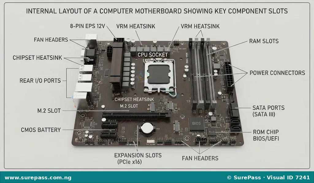
A motherboard is the main printed circuit board in a computer that connects and allows communication between all other hardware components.
The motherboard acts as the central highway of the computer. It contains sockets for the processor, slots for memory modules, and ports for storage drives. It also features built-in pathways called buses, which carry electrical signals and data between the different components.
The Central Processing Unit
A Central Processing Unit is the primary electronic chip in a computer that executes instructions and processes data.
Often referred to as the brain of the computer, the CPU performs all arithmetic calculations and logical decisions. It fetches instructions from the computer memory, decodes them, and executes the required operations. The speed of a CPU is measured in Gigahertz (GHz), which indicates how many billions of calculations it can perform per second.
Random Access Memory
Random Access Memory is a volatile temporary storage medium that holds data and instructions currently being used by the active operating system and open applications.
RAM is high-speed memory that allows the CPU to read and write data almost instantly. It is described as volatile because it requires electrical power to maintain its data. When the computer is turned off, all information stored in the RAM is completely lost.
Read-Only Memory
Read-Only Memory is a non-volatile permanent storage medium that contains pre-recorded instructions used to boot up the computer.
ROM contains the Basic Input/Output System (BIOS) or Unified Extensible Firmware Interface (UEFI). These essential instructions check the computer hardware when it is turned on and load the operating system. ROM is non-volatile, meaning it retains its data even when the computer is powered down.
Storage Drives
A storage drive is a non-volatile hardware device used to store user data, applications, and the operating system permanently.
Unlike RAM, storage drives retain data when the computer is turned off. There are two main types of storage drives used in modern computers:
- Hard Disk Drives (HDD): These use spinning magnetic platters and a moving read/write head to store and retrieve data. They offer large storage capacities at a lower cost but are slower and more prone to physical damage.
- Solid State Drives (SSD): These use flash memory chips to store data electronically. They have no moving parts, making them much faster, quieter, and more durable than traditional hard drives.
The Power Supply Unit
A Power Supply Unit is a hardware component that converts alternating current from a wall outlet into regulated direct current power for the internal components of a computer.
The PSU receives high-voltage alternating current (AC) from the mains electricity supply and converts it into low-voltage direct current (DC) required by the motherboard, processor, and storage drives. It features a bundle of cables with specialized connectors to distribute power safely to each component.
Observe the diagram below to see how these components are arranged on a computer motherboard.
Internal Components of a Mobile Phone
Mobile phones contain internal components that perform similar functions to those in a computer, but they are designed to be much smaller, lighter, and more energy-efficient.
The main internal components of a mobile phone are:
- The Logic Board
- The System on Chip (SoC)
- Mobile RAM
- Mobile Storage (Flash Memory)
- The Battery and Power Management IC (PMIC)
The Logic Board
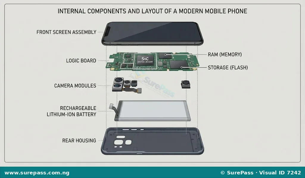
A logic board is the main printed circuit board inside a mobile phone that holds and connects all the essential electronic components.
The logic board is the mobile equivalent of a computer motherboard. Because mobile phones are compact, the logic board is highly integrated. It holds the processor, memory, wireless antennas, camera connectors, and charging ports on a single, multi-layered board.
The System on Chip
A System on Chip is an integrated circuit that combines the CPU, graphics processor, memory controllers, and wireless modems onto a single physical chip.
In mobile phones, space is limited. Instead of having a separate CPU, graphics card, and network card, manufacturers combine these parts into a single chip called the SoC. This integration reduces power consumption, generates less heat, and allows mobile phones to be extremely thin.
Mobile RAM and Storage
Mobile Random Access Memory is low-power volatile memory used to store active application data for quick access by the mobile processor.
Mobile storage is non-volatile flash memory used to store the mobile operating system, applications, and user files permanently.
In mobile phones, both RAM and storage are soldered directly onto the logic board to save space. Mobile phones use specialized flash storage technologies, such as embedded MultiMediaCard (eMMC) or Universal Flash Storage (UFS), which are designed for high speed and low power consumption.
The Battery and Power Management IC
A Power Management Integrated Circuit is a specialized microchip that regulates and distributes electrical power from the battery to the various components of a mobile phone.
Mobile phones rely on a rechargeable Lithium-Ion or Lithium-Polymer battery for power. The PMIC controls the charging process, prevents the battery from overcharging, and ensures that each component on the logic board receives the exact voltage it needs to operate safely.
Look at the diagram below to see the internal layout of a mobile phone.
Relationships Among the Components
The internal components of computers and mobile phones do not work in isolation. They form an interconnected system where each part relies on the others to perform tasks.
The relationship and interaction among these components can be understood through the following processes:
- Power Distribution: The Power Supply Unit (in computers) or the Battery and PMIC (in mobile phones) provides electrical energy to the motherboard or logic board. The board then distributes this power to the CPU, RAM, ROM, and storage drives.
- The Boot Process: When the device is powered on, the CPU activates and reads the initial startup instructions stored permanently in the ROM. These instructions tell the CPU how to initialize the hardware.
- Loading the Operating System: Once the hardware is checked, the CPU instructs the storage drive (SSD, HDD, or Flash memory) to copy the operating system files into the high-speed RAM.
- Running Applications: When an application is opened, its data is loaded from the permanent storage drive into the temporary RAM. The CPU then fetches instructions from the RAM, processes them, and sends the results back to the RAM to update the display.
- Saving Data: When a user saves a document, photo, or file, the CPU transfers the data from the volatile RAM back to the non-volatile storage drive for permanent storage.
The diagram below illustrates how data and power flow among these components during operation.
Practical Guide to Identifying Components
Developing the skill to identify internal components is essential for hardware maintenance, troubleshooting, and repairs.
Identifying Computer Components
This procedure describes how to safely open a computer system unit and identify its internal parts.
The required tools and safety materials are:
- A Phillips-head screwdriver
- An anti-static wrist strap
- An anti-static mat
The procedure involves the following steps:
- Shut down the computer completely and unplug the power cable from the wall outlet.
- Press and hold the power button for five seconds to discharge any remaining electrical energy in the capacitors.
- Wear the anti-static wrist strap and connect its clip to a metal part of the computer chassis to prevent electrostatic discharge from damaging sensitive chips.
- Use the screwdriver to remove the screws securing the side panel of the system unit casing, and slide the panel off.
- Locate the motherboard, which is the large circuit board mounted flat against the side or bottom of the case.
- Identify the CPU cooling fan and heatsink assembly; the CPU itself is secured directly underneath this metal cooling structure.
- Locate the RAM modules, which are long, thin rectangular circuit boards inserted vertically into slots next to the CPU.
- Identify the storage drive, which is a rectangular metal box mounted in a drive bay and connected to the motherboard by a flat data cable.
- Locate the Power Supply Unit, which is a heavy metal box with a bundle of multi-coloured wires, positioned at either the top-rear or bottom-rear of the casing.
Identifying Mobile Phone Components
This procedure describes how to identify the internal parts of a mobile phone after the casing has been opened by a technician.
The required tools are:
- A plastic opening tool (spudger)
- A precision screwdriver set
The procedure involves the following steps:
- Ensure the mobile phone is powered off completely.
- Remove the back cover of the phone carefully using the plastic opening tool.
- Identify the battery, which is the largest, flat, rectangular component occupying most of the space inside the phone.
- Locate the logic board, which is the compact, green or black printed circuit board positioned at the top or surrounding the battery.
- Identify the System on Chip (SoC), which is the largest square chip on the logic board, often covered by a thin metal shield to prevent electromagnetic interference.
- Identify the camera modules, which are small square components with glass lenses connected to the logic board by flexible ribbon cables.
Guide to Drawing Hardware Components
Drawing hardware components helps in understanding their physical structure, pin layouts, and connection points.
Drawing a RAM Module
A RAM module can be represented as a long rectangle with gold contact pins and memory chips.
The steps to draw a simple RAM module are:
- Draw a long, thin horizontal rectangle to represent the printed circuit board.
- Draw a series of small, evenly spaced vertical lines along the bottom edge of the rectangle to represent the gold contact pins.
- Draw a small semi-circular notch near the middle of the bottom edge to represent the keying notch.
- Draw four to eight small, identical squares inside the main rectangle to represent the physical memory chips (DRAM chips).
- Label the drawing clearly with pointers indicating the “PCB”, “Memory Chips”, and “Gold Contact Pins”.
Drawing a CPU
A CPU can be represented as a square chip with a metal heat spreader on top and contact pads on the bottom.
The steps to draw a simple CPU are:
- Draw a perfect square to represent the outer substrate of the processor.
- Draw a slightly smaller square inside the first square to represent the integrated heat spreader (the metal lid).
- Draw a small triangle or dot in one of the outer corners to represent the alignment key (Pin 1 indicator).
- Draw small grid lines or dots on the underside view to represent the contact pads (Land Grid Array) or pins (Pin Grid Array).
- Label the drawing with pointers indicating the “Substrate”, “Heat Spreader”, and “Alignment Key”.
Drawing a Storage Drive
A storage drive can be represented as a rectangular box with data and power connectors.
The steps to draw a simple storage drive are:
- Draw a thick rectangular box to represent the drive casing.
- Draw a smaller rectangular plate on the top surface to represent the drive cover.
- At one of the short ends, draw two small L-shaped connector ports to represent the SATA data and power interfaces.
- Draw four small circles at the corners of the casing to represent the mounting screw holes.
- Label the drawing with pointers indicating the “Drive Casing”, “SATA Data Port”, and “SATA Power Port”.
Observe the simple line drawings below to guide your sketches.
Summary of Component Functions
The table below provides a comparative summary of the internal components found in computers and mobile phones, along with their primary functions.
| Component Type | Computer Equivalent | Mobile Phone Equivalent | Primary Function |
|---|---|---|---|
| Main Circuit Board | Motherboard | Logic Board | Connects all components and allows them to communicate. |
| Primary Processor | Central Processing Unit (CPU) | System on Chip (SoC) | Executes instructions and processes data. |
| Temporary Memory | Random Access Memory (RAM) | Mobile RAM (LPDDR) | Holds active data and programs for fast access by the processor. |
| Startup Memory | ROM (BIOS/UEFI Chip) | ROM (Bootloader) | Stores permanent instructions needed to boot the device. |
| Permanent Storage | Hard Disk Drive (HDD) / Solid State Drive (SSD) | Flash Memory (eMMC / UFS) | Stores the operating system, applications, and user files permanently. |
| Power Management | Power Supply Unit (PSU) | Battery and Power Management IC (PMIC) | Converts, regulates, and distributes electrical power to the system. |




0 comments
Open the discussion when you need it. Comments stay collapsed until requested so the initial article remains light.