



ARTICLE CONTENTSOn this page 11 sections
Components of GSM Phones
Performance Objectives
By the end of the lesson, students should be able to:
- identify hardware components of GSM;
- state software components of mobile phone;
- state functions of components of GSM;
- describe how the GSM components respond during operation.
Introduction to GSM Phone Components
A Global System for Mobile Communications (GSM) phone is a sophisticated electronic device that combines hardware and software to facilitate wireless communication, data processing and execution of user applications.
To understand how a mobile phone works, it is necessary to divide it into two main categories: hardware components and software components. Both categories must work in perfect harmony for the device to power on, connect to a cellular network and perform daily tasks.
Meaning of GSM Hardware
GSM phone hardware refers to the physical, tangible parts of a mobile phone that can be seen, touched and handled.
These physical parts are assembled inside the phone casing and are responsible for electrical connections, signal transmission, power supply and user interface interactions.
Meaning of GSM Software
GSM phone software refers to the set of invisible instructions, programs and operating systems that control the hardware and enable the phone to perform specific tasks.
Without software, the hardware components remain inactive and cannot perform any communication or computational functions.
Hardware Components of GSM Phones
The hardware of a GSM phone consists of several electronic and mechanical parts. Each part has a specific design and location on or within the phone structure.
The primary hardware components include:
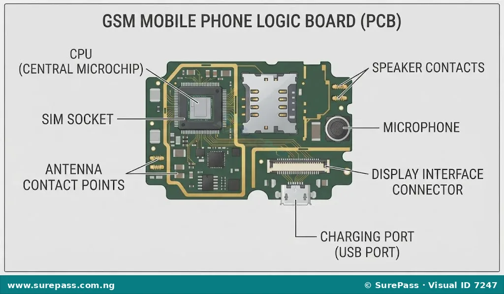
- Logic Board (Printed Circuit Board – PCB): This is the main circuit board of the phone. It acts as the brain’s pathway, holding and connecting all the vital electronic components such as the CPU, memory chips, resistors and capacitors.
- Central Processing Unit (CPU): Often referred to as the processor, the CPU is the main microchip on the logic board that executes instructions, processes data and coordinates the activities of all other hardware components.
- Subscriber Identity Module (SIM) Socket: This is a small slot on the logic board designed to hold the SIM card. It contains metallic contact pins that read the data stored on the SIM card, allowing the phone to connect to a specific mobile network provider such as MTN, Airtel, Glo or 9mobile.
- Earpiece: This is a small speaker located at the top front part of the phone. It converts electrical audio signals from incoming calls into sound waves that can be heard when the phone is held to the ear.
- Keypad: Found mostly in feature phones, the keypad is an input interface consisting of physical buttons used to dial numbers, type messages and navigate the phone menu. In modern smartphones, this physical keypad is replaced by a virtual keypad on the touch screen.
- Microphone: This is a small audio input transducer located at the bottom of the phone. It captures the voice of the user and converts sound waves into electrical signals to be transmitted over the network.
- Speaker (Loudspeaker): This is a larger audio output component located at the back or bottom of the phone. It is used to play ringtones, music, system alerts and voice audio during hands-free calls.
- Antenna: This is a metallic component, often embedded within the phone casing or printed directly onto the logic board, designed to transmit and receive radio frequency (RF) signals to and from network base stations.
- Display Interface: This is the connection port and circuitry that links the display screen (LCD or OLED) to the logic board, allowing the CPU to send visual data, images and text to the screen.
- Battery: This is the rechargeable power source of the phone, usually made of Lithium-Ion (Li-Ion) or Lithium-Polymer (Li-Po), which provides the direct current (DC) voltage required to power the electronic circuits.
- Charging Pot (Charging Port): This is the female connector interface (such as Micro-USB or USB Type-C) where the external charger is plugged in to replenish the battery power.
Observe the diagram below showing the layout of these hardware components on a typical GSM phone logic board.
Software Components of GSM Phones
The software components of a mobile phone provide the instructions that tell the hardware what to do. Mobile phone software is generally classified into two main levels:
- Operating System (OS): This is the system software that manages the phone’s hardware resources, memory, files and processes. It provides the user interface and acts as a platform for running applications. Common mobile operating systems include Android (used by brands like Tecno, Infinix, Samsung and Itel), iOS (used by Apple iPhones) and KaiOS (used by smart feature phones).
- Application Software (Apps): These are programs designed to perform specific tasks for the user. Examples include web browsers (Opera Mini, Google Chrome), instant messaging applications (WhatsApp), social media apps, mobile banking apps, utility tools (calculator, calendar) and games.
Functions of GSM Components
To understand how a GSM phone operates, it is necessary to examine the specific function of each hardware and software component. The table below outlines these functions clearly:
| Component Name | Type | Primary Function |
|---|---|---|
| CPU | Hardware | Processes instructions, performs calculations and controls all other hardware parts. |
| Logic Board | Hardware | Provides physical support and electrical pathways to connect all electronic components. |
| SIM Socket | Hardware | Holds the SIM card securely and connects its microchip to the phone’s circuitry for network identification. |
| Antenna | Hardware | Receives incoming radio signals from network masts and transmits outgoing radio signals. |
| Microphone | Hardware | Converts the user’s voice (sound waves) into electrical signals during a call or recording. |
| Earpiece | Hardware | Converts incoming electrical voice signals into audible sound waves for private listening. |
| Speaker | Hardware | Produces loud audio outputs for ringtones, media playback and speakerphone mode. |
| Display Interface | Hardware | Transmits visual data from the logic board to the screen for user viewing. |
| Keypad / Touch Screen | Hardware | Accepts physical or touch inputs from the user to control the device. |
| Battery | Hardware | Stores and supplies electrical energy to power the entire phone. |
| Charging Pot | Hardware | Receives electrical current from an external charger to recharge the battery. |
| Operating System (OS) | Software | Manages hardware resources, controls memory allocation and provides the user interface. |
| Application Software | Software | Enables the user to perform specific tasks like browsing, messaging and gaming. |
How GSM Components Interact During Operation
GSM components do not work in isolation. They must constantly communicate and interact with one another to perform any action. This interaction can be observed during common phone operations.
1. The Interaction During a Voice Call
When a user makes a voice call, the components respond in a coordinated sequence:
- Input Stage: The user dials a phone number using the keypad or touch screen. The display interface immediately updates the screen to show the dialed digits.
- Processing Stage: The CPU registers the input and requests network authorization from the SIM card via the SIM socket. The operating system coordinates this request.
- Transmission Stage: Once authorized, the CPU instructs the antenna to send out radio frequency signals to search for the nearest network base station and establish a connection.
- Audio Conversion Stage: When the call is connected, the user speaks into the microphone. The microphone converts the voice into electrical signals, which the CPU processes and sends to the antenna for transmission.
- Reception Stage: Simultaneously, the antenna receives incoming radio signals from the other caller. The CPU decodes these signals and sends them to the earpiece or speaker, which converts them back into audible sound.
Look at the process sequence diagram below to see how these components interact during a call.
CPU Processing -> SIM Authentication (SIM Socket) -> Signal Transmission (Antenna) -> Audio Capture (Microphone) -> Audio Output (Earpiece/Speaker). Arrows indicate the direction of data and signal flow. alt: Flowchart showing the step-by-step interaction of GSM components during a phone call. caption: Component interaction sequence during a voice call. aspect_ratio: 4:3 –>2. The Interaction During Phone Boot-up (Powering On)
When the power button is pressed, another set of interactions occurs:
- The battery releases electrical current through the power management circuit on the logic board.
- The CPU wakes up and loads the bootloader instructions from the phone’s permanent memory.
- The CPU initializes the hardware components, checking if the display interface, SIM socket and antenna are functioning.
- The Operating System (OS) is loaded into the temporary memory (RAM), and the startup logo is displayed on the screen via the display interface.
- The SIM socket reads the SIM card, and the antenna searches for network signals, displaying the network bars on the screen once connected.
How to Identify GSM Components (Practical Guide)
Identifying GSM components requires careful observation of their physical shapes, sizes, locations and connection points on the phone’s logic board.
The following steps outline how to identify these components safely on a disassembled mobile phone:
The required tools and materials are:
- A non-working or dummy GSM mobile phone (for practice)
- A precision screwdriver set
- A plastic opening tool (spudger)
- An anti-static wrist strap (or ESD mat)
The identification procedure involves the following steps:
- Preparation: Put on the anti-static wrist strap to prevent electrostatic discharge from damaging the electronic components. Ensure the phone is completely powered off.
- Battery Removal: Remove the back cover of the phone. If the battery is removable, slide it out. Observe the metallic battery terminals on the phone that connect to the battery contacts.
- Disassembly: Use the appropriate precision screwdriver to remove the screws holding the inner frame. Carefully separate the front and back housings using the plastic opening tool to expose the logic board.
- Identifying the SIM Socket: Look for a metallic, rectangular holder on the logic board. It usually has a slot wide enough to fit a micro or nano SIM card and contains small gold-plated spring pins inside.
- Identifying the CPU: Locate the largest square or rectangular black microchip soldered directly onto the logic board. It is often covered by a metallic shield (EMI shield) to prevent signal interference.
- Identifying the Antenna: Look at the top or bottom edges of the phone housing. The antenna appears as copper or gold-plated metallic tracks printed on the plastic frame or directly on the edges of the logic board.
- Identifying the Microphone: Look at the very bottom of the logic board for a tiny, round, silver or black component with a small hole in the center. This hole allows sound waves to reach the internal diaphragm.
- Identifying the Earpiece and Speaker: Locate the small rectangular or circular speaker at the top of the phone frame (earpiece) and the larger speaker module at the bottom (loudspeaker). They contain small magnets and copper coils.
- Identifying the Charging Pot: Look at the bottom edge of the logic board for a small metal-shielded port with internal pins where the charging cable connects.
- Reassembly: Carefully place the logic board back into the housing, tighten the screws, insert the battery and replace the back cover.
Important safety tips during component identification include:
- Do not use excessive force when prying open the phone housing to avoid cracking the display screen or tearing internal ribbon cables.
- Never puncture or bend a lithium-ion battery, as this can cause a chemical fire or explosion.
- Keep all tiny screws organized in a small tray so they are not lost during the process.
Summary of Differences Between Hardware and Software
To easily distinguish between hardware and software components, the following key differences should be noted:
- Physicality: Hardware is physical and can be touched, whereas software is virtual and cannot be touched.
- Damage: Hardware components suffer from physical wear and tear, liquid damage or breakage. Software components suffer from corruption, bugs, viruses or operating system crashes.
- Replacement: Damaged hardware must be physically repaired or replaced using tools like soldering irons. Damaged software is corrected by reinstalling, updating, flashing or resetting the program.




0 comments
Open the discussion when you need it. Comments stay collapsed until requested so the initial article remains light.