


ARTICLE CONTENTSOn this page 5 sections
Robot Design I (Obstacle-Avoidance Robot)
Performance Objectives
By the end of the lesson, students should be able to:
- explain robot design and automation,
- describe the steps in building a robot;
- Build a two-wheel differential drive system mobile robot.
Understanding Robot Design and Automation
What is Robot Design?
Robot design is the process of creating robots. This involves planning, developing, and constructing machines that can perform tasks automatically or semi-automatically. It includes choosing the right components, arranging them, and programming the robot to achieve a specific purpose.
What is Automation?
Automation is the use of technology to perform tasks with minimal human intervention. Automated systems can operate without constant human control, making processes more efficient, faster, and sometimes safer.
Relationship Between Robot Design and Automation
Robot design is a key part of automation. Robots are often designed to automate tasks that are repetitive, dangerous, or require high precision. For example, a robot designed to assemble car parts in a factory is an example of automation. The robot performs the assembly task automatically, reducing the need for human workers to do the same repetitive work.
Steps in Building a Robot
Building a robot involves a systematic approach to ensure the final product meets its intended purpose. The following steps outline the general process:
1. Identify the Type of Robot
The first step is to decide what kind of robot is needed. Different tasks require different robot structures. For an obstacle-avoidance robot, a common and effective type is the two-wheel differential drive system. This system uses two main wheels, each driven by its own motor, and a free-spinning castor wheel for balance. This design allows the robot to move forward, backward, and turn by varying the speed and direction of the two main wheels.
2. Determine the Purpose and Select Components
Once the robot type is identified, its specific purpose must be clearly defined. For an obstacle-avoidance robot, the purpose is to move around an environment without colliding with objects. Based on this purpose, the necessary components are selected. These components include the brain of the robot (microcontroller), parts for movement (motors, wheels, chassis), power source, and sensors to detect obstacles.
3. Assemble Components
After selecting all the components, they are physically put together. This involves attaching the motors to the chassis, mounting the wheels, connecting the microcontroller, motor driver, and sensors, and ensuring all parts are securely fastened. Proper assembly is crucial for the robot’s stability and functionality.
4. Test and Calibrate
Once assembled, the robot needs to be tested to ensure all its parts work correctly. Calibration involves fine-tuning the robot’s movements and sensor readings. For example, motor speeds might need adjustment to ensure the robot moves in a straight line, and sensor sensitivity might need to be set so it accurately detects obstacles at the desired distance. This step helps to correct any errors and optimise the robot’s performance.
Building a Two-Wheel Differential Drive System Mobile Robot
This section details the practical steps and components involved in building a basic obstacle-avoidance robot using a two-wheel differential drive system.
Essential Components for the Robot
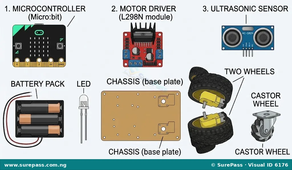
The following components are typically used to build a two-wheel differential drive obstacle-avoidance robot:
- Microcontroller: This is the “brain” of the robot. It receives input from sensors, processes information, and sends commands to other components like motors. Examples include Micro:bit v2, ESP32, or Raspberry Pi Pico.
- Motor Driver: This electronic circuit acts as an interface between the microcontroller and the motors. Microcontrollers cannot directly supply enough power to run motors, so a motor driver (e.g., TB6612FNG or L298N) is used to control the speed and direction of the motors using signals from the microcontroller.
- Chassis: This is the frame or body of the robot, providing a structure to mount all other components. It can be made from materials like acrylic, plastic, or metal.
- Wheels: Two main wheels are attached to the motors, allowing the robot to move.
- Castor Wheel: A small, free-spinning wheel, usually placed at the front or back of the chassis, provides stability and allows the robot to pivot easily.
- Power Supply: This provides electrical energy to all the robot’s components. It typically consists of batteries (e.g., AA batteries, LiPo batteries) and a battery holder.
- Ultrasonic/Bump Sensor: These are the “eyes” or “feelers” of the robot.
- An ultrasonic sensor (like HC-SR04) uses sound waves to detect the distance to objects, helping the robot “see” obstacles.
- A bump sensor (or tactile switch) detects physical contact with an obstacle.
- LED/Buzzer: These are output indicators. An LED (Light Emitting Diode) can light up to show the robot’s status (e.g., obstacle detected), while a buzzer can make a sound for the same purpose.
- Adhesives: Materials like screws, nuts, bolts, double-sided tape, or glue are used to securely attach components to the chassis.
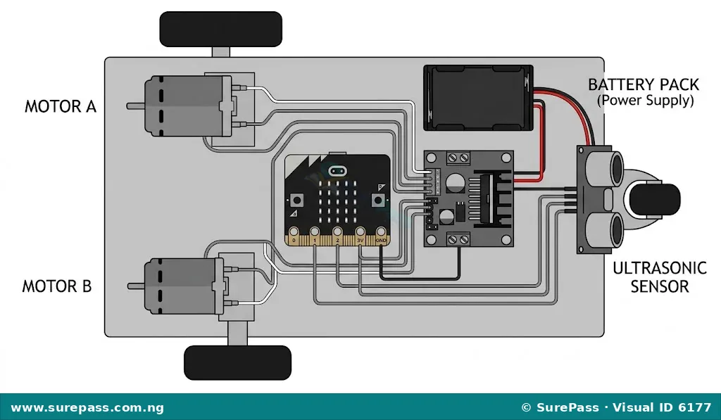
Assembling the Two-Wheel Chassis and Wiring Motor Driver Connections
Assembling the robot involves carefully attaching the physical parts and making the electrical connections. This process requires attention to detail to ensure all components are secure and wired correctly.
The procedure involves the following steps:
- Attach Motors to Chassis: Securely mount the two DC motors to the underside of the chassis, one on each side. Ensure they are positioned to drive the main wheels.
- Mount Wheels: Push the two main wheels onto the shafts of the motors.
- Attach Castor Wheel: Mount the castor wheel to the front or back of the chassis, ensuring it can rotate freely and supports the robot’s weight.
- Mount Microcontroller: Secure the microcontroller (e.g., Micro:bit, ESP32, Raspberry Pi Pico) to the top of the chassis using screws or double-sided tape.
- Mount Motor Driver: Place the motor driver module (e.g., TB6612FNG, L298N) on the chassis near the microcontroller.
- Connect Motors to Motor Driver: Connect the two wires from each DC motor to the output terminals of the motor driver. Typically, there are two output terminals for each motor (e.g., OUT1, OUT2 for Motor A; OUT3, OUT4 for Motor B).
- Connect Motor Driver to Microcontroller: Connect the input pins of the motor driver (e.g., IN1, IN2, IN3, IN4, ENA, ENB) to the digital output pins of the microcontroller. The ENA and ENB pins control the speed (using PWM), while IN1/IN2 and IN3/IN4 control the direction of each motor.
- Connect Power Supply: Connect the battery pack to the power input terminals of the motor driver (e.g., VCC/VM and GND). Also, connect the microcontroller’s power input (e.g., 3.3V or 5V and GND) to the appropriate power output from the motor driver or directly from the battery pack if it has a voltage regulator.
- Mount Sensor: Attach the ultrasonic or bump sensor to the front of the chassis.
- Connect Sensor to Microcontroller:
- For an ultrasonic sensor (HC-SR04), connect its VCC to 5V, GND to GND, Trig pin to a digital output pin on the microcontroller, and Echo pin to a digital input pin on the microcontroller.
- For a bump sensor, connect one terminal to a digital input pin on the microcontroller and the other to GND (or VCC, depending on the wiring).
- Connect LED/Buzzer (Optional): If using an LED or buzzer, connect one leg to a digital output pin on the microcontroller and the other leg (with a current-limiting resistor for LED) to GND.
Writing Modular Control Functions in MicroPython/Python
After assembly, the robot needs instructions to operate. These instructions are written as code, often using MicroPython or Python for microcontrollers. Using modular functions makes the code organised and easier to manage.
Modular control functions are small, reusable blocks of code that perform specific actions. For an obstacle-avoidance robot, essential functions include:
- `forward()`: This function commands both motors to spin in the direction that makes the robot move forward. It sets the appropriate input pins on the motor driver to high or low and enables the motors.
- `stop()`: This function commands both motors to stop spinning. It typically sets the enable pins of the motor driver to low or sets the input pins to a neutral state.
- `turn_left()`: This function makes the robot turn left. This can be achieved by spinning the right wheel forward and the left wheel backward, or by stopping the left wheel and spinning the right wheel forward.
- `turn_right()`: Similar to `turn_left()`, this function makes the robot turn right. This can be achieved by spinning the left wheel forward and the right wheel backward, or by stopping the right wheel and spinning the left wheel forward.
These functions are then called within the main program logic to control the robot’s movement.
Performing Speed Calibration and Straight-Line Testing
Even if two motors are identical, they might not spin at exactly the same speed when given the same command. This can cause the robot to drift or turn slightly when it should be moving straight. Calibration helps correct this.
- Straight-Line Testing: Place the robot on a flat surface and command it to move forward for a set distance or time. Observe if it moves in a perfectly straight line.
- Speed Calibration: If the robot drifts, adjust the power or speed setting for one of the motors until it moves straight. This might involve slightly reducing the power to the faster motor or increasing it for the slower motor. This adjustment is usually done in the code, for example, by setting different Pulse Width Modulation (PWM) values for each motor’s enable pin.
Integrating Sensor Input with If/Else Logic for Obstacle Avoidance
The core of an obstacle-avoidance robot lies in its ability to react to its environment using sensor data and decision-making logic.
- Read Sensor Data: The microcontroller continuously reads data from the ultrasonic or bump sensor.
- For an ultrasonic sensor, it measures the time it takes for a sound wave to travel to an object and return, then calculates the distance.
- For a bump sensor, it detects if the switch has been pressed.
- Apply If/Else Logic: The robot’s program uses `if/else` statements to make decisions based on the sensor readings.
- `If` the sensor detects an obstacle within a certain distance (e.g., less than 20 cm), the robot will execute a sequence of actions to avoid it.
- `Else` (if no obstacle is detected), the robot will continue its normal movement, such as moving forward.
- Obstacle Avoidance Sequence: When an obstacle is detected, the robot might perform actions like:
- Stop moving forward.
- Move backward for a short distance.
- Turn left or right for a certain duration.
- Then, continue moving forward.
Documenting the Build
Documentation is an important part of any engineering project. It helps others understand the robot’s design and allows for future improvements or troubleshooting.
- Parts List: A detailed list of all components used, including their names, quantities, and any specific models or specifications (e.g., “Micro:bit v2,” “L298N Motor Driver,” “2 x DC Gear Motors”).
- Labelled Wiring Diagram: A clear diagram showing how all the components are electrically connected, with labels for each wire and pin. This helps in understanding the circuit and troubleshooting connection issues.
- Calibration Data: Record the values or adjustments made during speed calibration. For example, “Left Motor PWM: 180, Right Motor PWM: 195” to achieve straight-line movement. This data is useful if the robot needs to be rebuilt or if performance issues arise.




0 comments
Open the discussion when you need it. Comments stay collapsed until requested so the initial article remains light.